AI PLC PROGRAMMING · IEC 61131-3
Write PLC logic in plain English. See it as ladder and function blocks. Prove it before it runs.
PLC-Ladder turns a sentence like “start the conveyor 5 seconds after the start button” into IEC 61131-3 Structured Text, converts the structured text to a ladder diagram and a function block diagram (FBD), and simulates it in your browser, checked by a deterministic compiler, not by guesswork.
Best on a laptop or desktop. On a phone you can try the simulator and read the diagrams; drafting and editing want a keyboard.
PROGRAM ConveyorVAR StartButton AT %IX0.0 : BOOL; StopButton AT %IX0.1 : BOOL; PartAtSt1 AT %IX0.2 : BOOL; Conveyor AT %QX0.0 : BOOL; Run : BOOL; Dwell : TON; (* PT assumed *)END_VARRun := (StartButton OR Run) AND NOT StopButton;Dwell(IN := PartAtSt1, PT := T#3S);Conveyor := Run AND NOT (PartAtSt1 AND NOT Dwell.Q);END_PROGRAMSee it work — 90 seconds
One sentence in, IEC 61131-3 Structured Text drafted, converted to a ladder diagram and a function block diagram, and simulated, all in one real session.
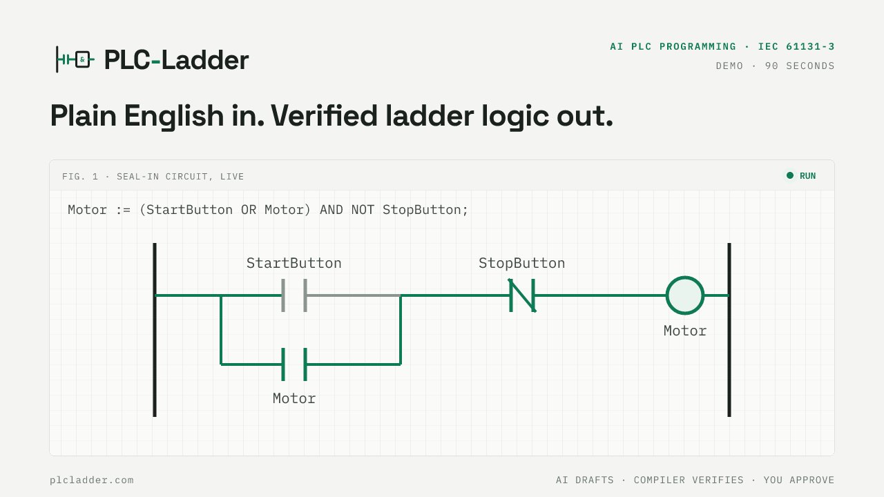
How plain English becomes verified ladder and function block logic
Describe
Say what the machine should do, in your own words. If the request is ambiguous (“stop it after a while”), the assistant asks instead of guessing.
Draft
AI writes IEC 61131-3 Structured Text, kept inside a published subset of the language that the compiler can fully verify.
Verify
A deterministic compiler (fixed rules, the same answer every time) parses the code, type-checks it, converts it to a ladder diagram and an IEC 61131-3 function block diagram, and runs a scan-cycle simulation.
Approve
You review the code, the ladder, the FBD, and the live simulation side by side. Nothing moves toward real equipment without your explicit sign-off.
Exportgated
Exports open format by format, each only after round-trip validation in the vendor's own tool, and only while every file compiles. The Export dialog shows what is open today.
OPC UA · AVAILABLE ON EVERY PLAN
Drive the verified logic from your own HMI
One click on Expose to SCADA gives your running simulation its own OPC UA endpoint, so any OPC UA client, such as Ignition, FactoryTalk View, WinCC or UaExpert, can run the same compiler-checked logic from the screens your operators will use, before any PLC is wired. Nothing to install.
Inputs you write, outputs you read
Every input is a node your HMI can write, and a write forces it. Outputs are read-only: the server refuses the write even from a client that ignores the access level.
Presets you can tune
Timer PT and counter PV presets are writable, so an operator screen can change a dwell time the way it would on the machine.
Secure by default
Basic256Sha256 with sign-and-encrypt only, a username and password, no anonymous access. Every session is isolated from every other.
Edit, and it reloads
Change the program in the workbench; once it compiles, the endpoint picks up the new logic and the node IDs stay the same, so your HMI tags keep working.
Endpoint: opc.tcp://opc.plcladder.com:4840 · one exposed session on the free plan.
| Node | Type | Access | Value |
|---|---|---|---|
| InputsStartButton | Boolean | read / write | false |
| StopButton | Boolean | read / write | false |
| PartAtSt1 | Boolean | read / write | true |
| OutputsConveyor | Boolean | read | false |
| TimersDwell.PT | Double | read / write | 3000 |
| Dwell.ET | Double | read | 2050 |
| StatusScanCount | Int64 | read | 118230 |
ns=<idx>;s=Conveyor.Inputs.StartButton · TIME in milliseconds · a write to an input forces itWho it's for
Automation engineers & technicians
Sketch and test control logic in seconds instead of waiting on the full edit-compile-download cycle. Convert structured text to ladder logic so the whole team (ST writers and ladder readers) sees the same verified model: ladder for the floor, FBD for the engineering review.
Students learning PLC programming
A free online PLC simulator with nothing to install: watch how a seal-in circuit latches, how series contacts make AND and parallel branches make OR, and how a scan cycle actually evaluates a rung. Then flip the view and watch how the same logic looks as function blocks: AND gates, OR gates, and timers wired left to right.
System integrators
Turn a customer's plain-English requirements into reviewable IEC 61131-3 starter code and a ladder diagram on the first call, then refine by hand. Faster quotes, faster first drafts.
The AI never writes the final artifact
This is the design rule the whole tool is built on. AI drafts; a rule-based compiler verifies; a human approves. When the compiler finds a problem, the error goes back to the AI to repair; it doesn't go to you, and it certainly doesn't go to a machine. In an industry where one wrong rung can stop a production line, trust has to come from architecture, not promises.
Frequently asked questions
Can AI really write PLC code?
It can draft it well, and that's exactly how PLC-Ladder treats it. The AI writes IEC 61131-3 Structured Text from your plain-English description, but a rule-based compiler (fixed rules, no AI) then parses, type-checks, and simulates every line. If the draft doesn't hold up, it never reaches you as a result. AI speed, compiler certainty. Inside a project the same rule scales up: the project agent reads every program and function block, proposes a change set (a new block used in three places, a rename across files, every stage delay +50 ms), the compiler verifies the whole project on a shadow copy, and you approve or reject the per-file diffs. Nothing is written until you approve.
What is ladder logic, in one sentence?
Ladder logic (LD) is the graphical PLC programming language that draws control logic as electrical rungs (contacts in series mean AND, parallel branches mean OR), and it's still how most technicians on the factory floor read and troubleshoot machine behaviour.
What is a function block diagram (FBD)?
A function block diagram is the IEC 61131-3 graphical language that draws control logic as connected blocks (AND/OR gates, timers, math blocks) with signal flowing left to right through wires. PLC-Ladder renders every verified program as both a ladder diagram and an FBD from the same compiled model, so the two views can never disagree.
What can the converter handle today?
The alpha covers the core of real-world control logic, rendered as ladder and FBD: boolean assignments (AND, OR, NOT), IF/THEN/ELSE, comparisons like Pressure < 80, MOVE blocks with EN/ENO for numeric assignments (live values on the IN and OUT pins, exactly as CODESYS draws them), TON on-delay timers, CTU / CTD counters, SR / RS bistable latches (set- or reset-dominant, drawn with their SET1 / RESET1 pins), and R_TRIG / F_TRIG edge detection — a one-scan pulse when a signal rises or falls, drawn as the IEC |P| / |N| contact with no visible plumbing. It also handles numeric math on REAL variables — + − × ÷ with SQRT, ABS, trig, quadrant-correct ATAN2, DEG/RAD, MIN/MAX/LIMIT — simulated live in the FBD view (math blocks are FBD-first). Complex and phasor computation works today through paired REAL variables (Re/Im or Mag/Ang) with one-click starter patterns for multiply, divide, and rect-to-polar conversion — plus a verified power-systems block library: symmetrical components (SYM_COMP), per-unit conversion (PER_UNIT), complex power (COMPLEX_POWER), and phasor magnitude/angle blocks, each catalogued in the workbench with the golden vectors its test suite verifies. It supports user-defined function blocks: define a FUNCTION_BLOCK once above the program, and the compiler verifies it once and instantiates it as many times as you like, each instance with its own state and its own CODESYS-style glyph (no recursion, no VAR_IN_OUT yet). Anything outside that subset is rejected with a clear message and a line number rather than converted wrongly; knowing what not to convert is part of the safety story.
Do I need to install anything or create an account?
Nothing to install: PLC-Ladder is an online PLC editor and simulator that runs in your browser. You create a free account (email + password; we verify your email with a 6-digit code — no links to click) to use the workbench; the free tier includes 1 project workspace and $5 of free AI credit (each AI answer uses what the model charges for it, typically $0.10 to $0.40; failed drafts are free) with unlimited compiling and simulating, and no card is required. When the free credit is used up you can buy more AI credit in $10 or $15 packs.
Can I edit the ladder diagram directly?
Yes, and it never gets out of sync with the code: switch the Ladder tab to Edit and click a contact, a coil or a network to toggle NO/NC, rename, add contacts in series or parallel, delete, change a coil to SET/RESET, add a network or reorder. Each click is a deterministic rewrite of the underlying Structured Text that is recompiled and round-trip checked before it is kept — the text stays the single source of truth, so the diagram and the code can never disagree.
Can I take the logic into my PLC tool?
Exports open format by format, and only after a real round-trip — imported into the target tool, built with zero errors, and behaviourally checked in its simulator against our own — has been recorded. Until then a format is visibly locked in the Export dialog, which always shows what is open today, and an export is only offered while the whole project compiles green. Nothing is ever faked as a native vendor file.
Can I connect my HMI or SCADA over OPC UA?
Yes, on every plan. In the workbench, Expose to SCADA gives your running simulation its own OPC UA endpoint (opc.tcp://opc.plcladder.com:4840). Your HMI can write the inputs, only read the outputs, and tune timer and counter presets; the connection is Basic256Sha256 sign-and-encrypt with a username and password. The free plan runs one exposed session at a time. PLC-Ladder never connects to a real PLC.
Is AI-generated logic safe to put on a real machine?
Treat everything PLC-Ladder produces as an engineering draft. The compiler proves it parses, types, and simulates correctly, but final validation on real equipment always belongs to a qualified engineer. The tool is built around that principle: nothing is ever exported without explicit human approval.