 PLC-Ladder
How a structured text to ladder logic converter really works (parse, model, render), why hand translation drifts, and what the diagram can and cannot prove about your intent. Worked example: the three-wire start/stop circuit.
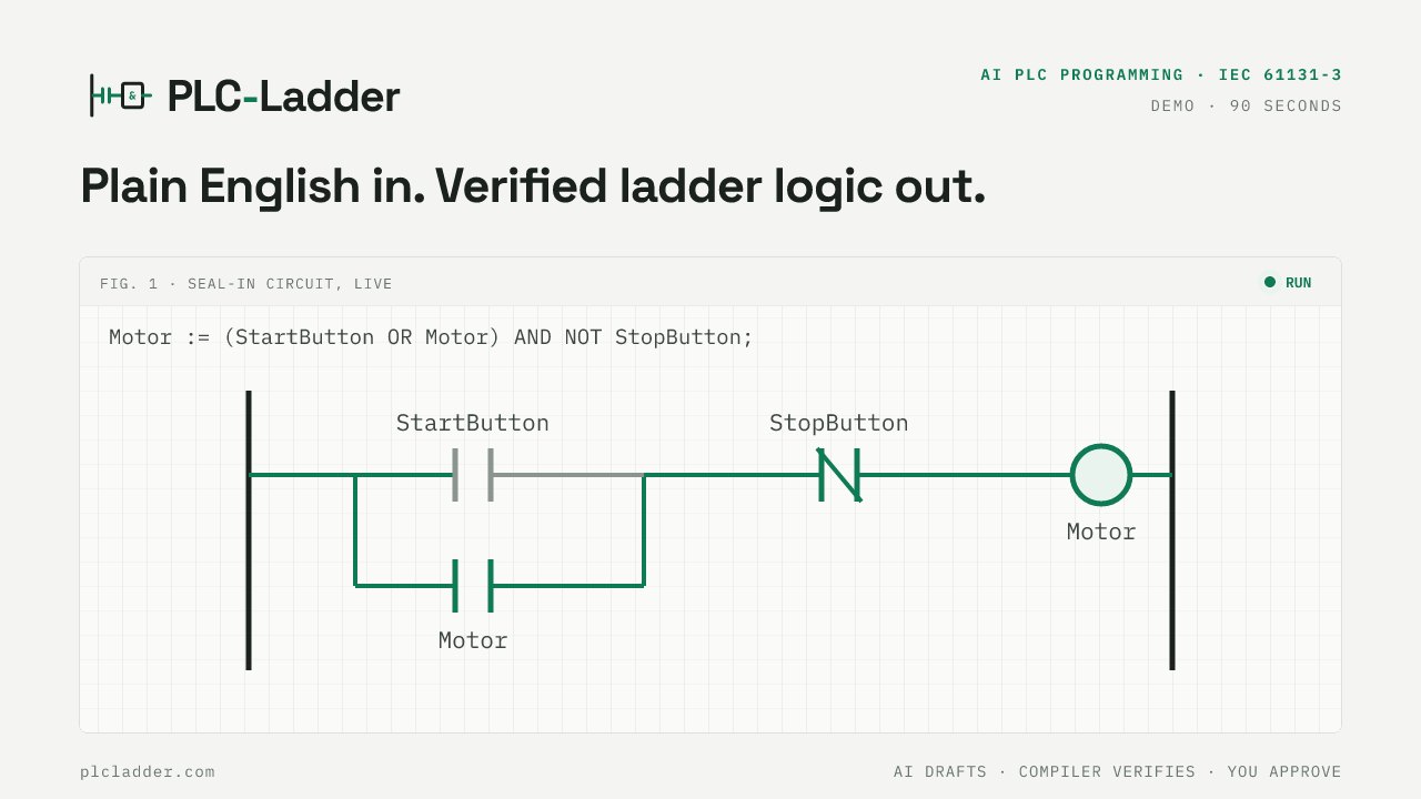
Most plants run on two languages at once. The engineer who designed the logic thinks in structured text, because conditions, timers and setpoints are easier to write as lines than as rungs. The technician who gets called at two in the morning reads ladder, because a rung is a circuit and a circuit can be traced with a meter. A structured text to ladder logic converter exists to keep those two people looking at the same logic. This post explains what one actually does, why translating by hand tends to drift, and, more importantly, what a converted diagram can and cannot prove.
Two languages, one piece of logic
IEC 61131-3 defines both languages, and any control behaviour you can draw as a rung can be written as an assignment. Series contacts are AND, parallel branches are OR, a normally-closed contact is NOT, a coil is the variable on the left of :=. Timers and counters are function blocks in both. The languages are different views, not different logic.
The problem is that the views are maintained separately. The engineer edits the text, the ladder printout in the panel is from last year's commissioning, and the two disagree in ways nobody notices until a fault. A converter removes the second copy: there is one source, and the ladder is derived from it every time it changes.
How a structured text to ladder logic converter actually works
Every converter we know of, including ours, does three things in order.
Parse. The text is read by a grammar for structured text, exactly as a compiler would read it. This is where syntax errors, undeclared variables and unsupported constructs are caught, with a line number. A good converter refuses here rather than guessing; a loop or an array has no faithful rung, and a diagram that looks right but means something else is worse than an error.
Model. The parsed program is turned into an intermediate representation, a list of networks. A network is one output: a coil plus everything that drives it. Motor := (StartButton OR Motor) AND NOT StopButton; becomes one network with two parallel branches, each ending in a normally-closed StopButton contact. IF Start THEN Motor := TRUE; END_IF; becomes a network with a SET coil. A timer call becomes a network whose tail holds a TON block. The model knows nothing about pixels; it knows contacts, branches, blocks and coils.
Render. The model is drawn. Ours draws it twice, as a ladder and as a function block diagram, from the same model, so the two views cannot disagree. The renderer is where CODESYS-style comparator blocks, MOVE blocks with EN and ENO, and counter blocks get their shape. If you have ever used a ladder diagram maker and wondered why the rungs look the way they do, the answer is usually a choice made at this stage.
The order matters. Because the model sits between parsing and drawing, the same model can also be simulated. That is what turns a converter into something you can verify, rather than something that merely draws.
Why hand translation drifts
People translate structured text into ladder by hand all the time, and the results are mostly right, which is the problem. The errors are small and specific.
Operator precedence is the classic one. A OR B AND C means A OR (B AND C), so the rung is two branches, one of them a series pair. Drawn from memory it often comes out as three contacts in series, or as (A OR B) AND C, both of which pass a quick glance.
NOT over a bracket is the second. NOT (A AND B) is not a single normally-closed contact; it is two normally-closed contacts in parallel. Our converter applies De Morgan's law automatically and draws the two branches, which surprises people the first time and is correct.
The third is the one that bites during commissioning: an IF with an ELSE is two networks, a SET and a RESET, not one rung with one coil. Write the same behaviour as a plain assignment and it is one rung. Both are valid; they differ in what happens when both conditions are true on the same scan, and a hand translation quietly picks one. We wrote up the rules in how to count networks in ladder logic.
Worked example: the three-wire start/stop circuit
The three-wire circuit is the rung every apprentice learns: a momentary start button, a momentary stop button, and a motor that stays running after the start button is released. In structured text it is one line, with an assumption stated where the drafter would state it:
PROGRAM Main
VAR
    StartButton : BOOL;
    StopButton  : BOOL;
    Motor       : BOOL;
END_VAR
// Assuming StopButton is TRUE while the stop button is pressed.
Motor := (StartButton OR Motor) AND NOT StopButton;
END_PROGRAM
Paste that into the workbench at PLC-Ladder and the ladder tab draws the circuit you expect: StartButton in parallel with a Motor contact, a normally-closed StopButton in series, and the Motor coil on the right rail. The Motor contact feeding its own coil is the seal-in.
[SCREENSHOT: Ladder tab showing the single seal-in network for the three-wire circuit, StartButton and Motor in parallel, NC StopButton in series, Motor coil]
Now run it. Open the rail, force StartButton on, and the coil energises. Force it off again and the coil stays on, because the Motor contact is now carrying the current. Force StopButton on and the rung opens. That two-second test is the difference between a drawing and a verified circuit: the seal-in either holds or it does not.
[SCREENSHOT: the same network with StartButton released and Motor still energised, the Motor contact highlighted as the conducting branch]
Compare it with the line a hurried translation sometimes produces:
Motor := StartButton AND NOT StopButton;
It compiles, it draws a tidy rung, and the motor stops the moment the operator lets go of the button. Both diagrams are correct translations of their text. Only one is the circuit that was meant.
What a converter can and cannot verify
A converter proves that the diagram matches the text. Ours goes further and proves the text is in a subset it can simulate, and the simulation shows what the logic does on each scan. That is a lot, and it is the whole basis of how we treat generated code: the AI drafts, the compiler proves the draft is well-formed and simulable, and a person approves it.
What no converter can verify is intent. Look at the assumption comment in the example. In a real three-wire circuit the stop button is wired normally-closed, so the PLC input is TRUE while nobody is pressing it, and the correct rung uses a normally-open contact of that input, not a normally-closed one:
// Assuming StopHealthy is wired normally-closed: TRUE while nobody presses stop.
Motor := (StartButton OR Motor) AND StopHealthy;
Both programs are valid. Both convert cleanly. They are opposite in the field, and the difference lives in the wiring diagram, not in either language. A converter cannot see the panel; it can only make the assumption visible so that the person who can see the panel checks it. That is why we insist on the assumption lines, and why the ladder is something you review and then simulate, rather than something you print and trust.
If you want to try the example without installing anything, see creating ladder diagrams online, and for what to test before the logic goes anywhere near hardware, testing ladder logic in an online PLC simulator.